Bienvenue sur perbal.net
posté le 06.02.08
Cliquez sur les rubriques de gauche pour accéder directement aux informations qui vous intéressent.
Accueil
Musique
Graphisme
Electronique
perbal.net
Liens
Email: 
Facebook 
Behance 
SoundCloud 
3D Pixel Art
Drumtraks Schematics
Thévenin
Statistiques Winamp
Bienvenue sur perbal.net
posté le 06.02.08
Cliquez sur les rubriques de gauche pour accéder directement aux informations qui vous intéressent.
3D Pixel Art
posté le 05.10.2014, mis à jour le 16.10.2023

3D Pixel Art by Bernard Perbal is licensed under a Creative Commons Attribution-ShareAlike 4.0 International License.
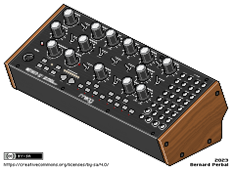

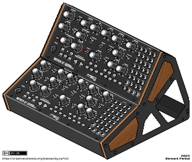
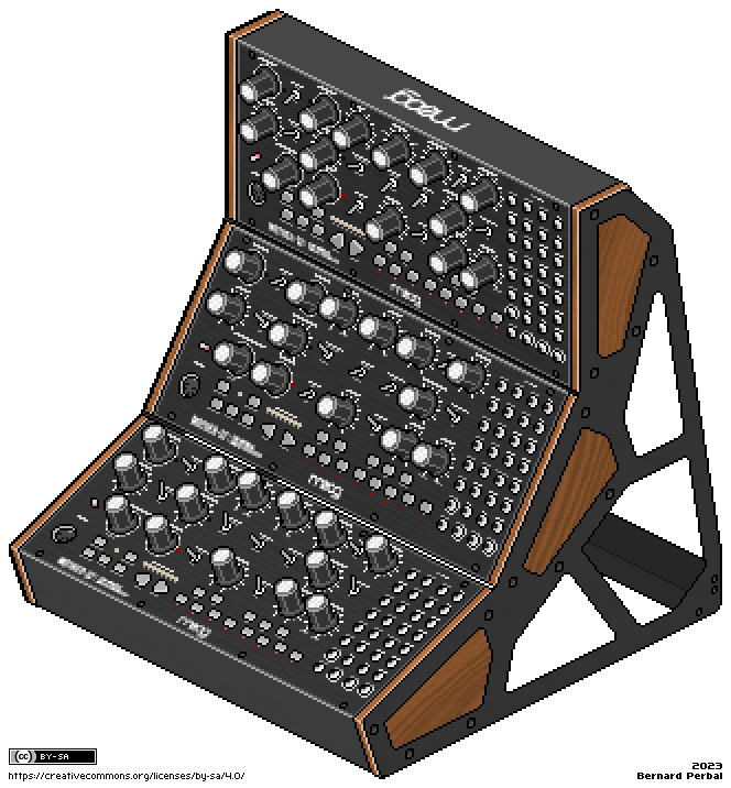
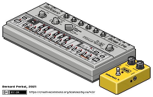
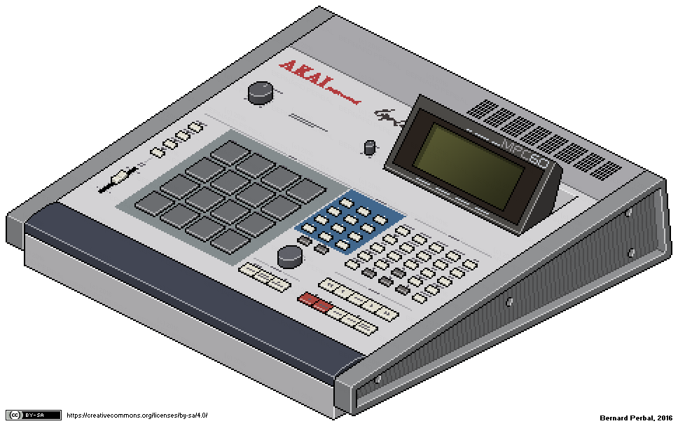
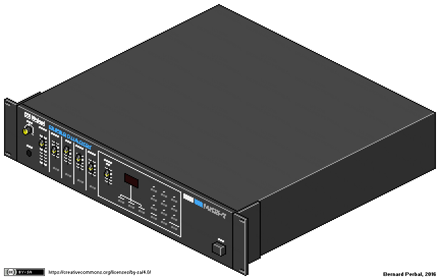
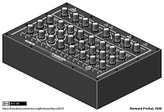
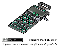
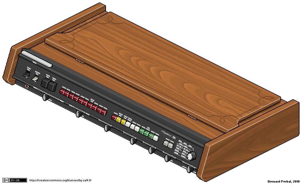
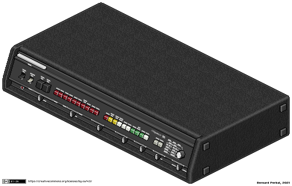
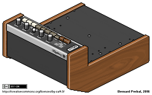
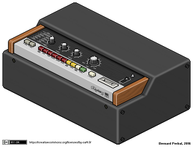
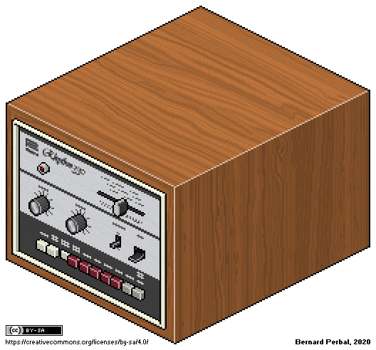
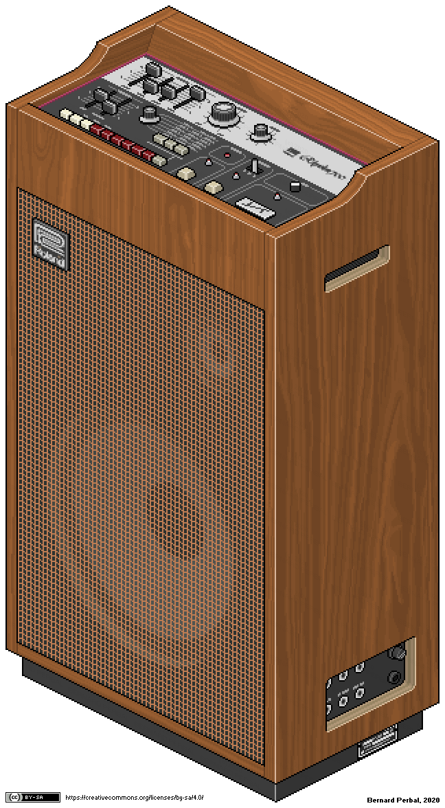
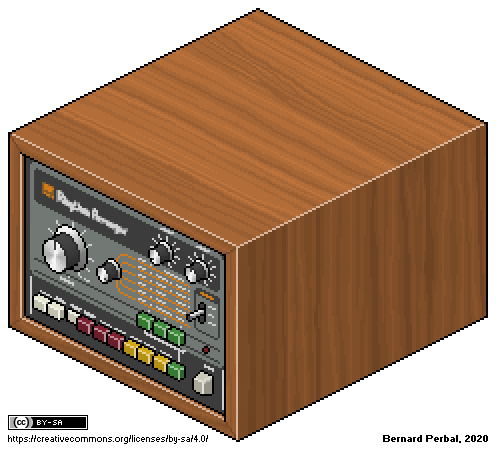
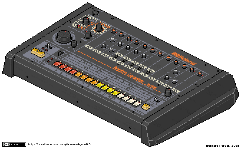
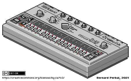
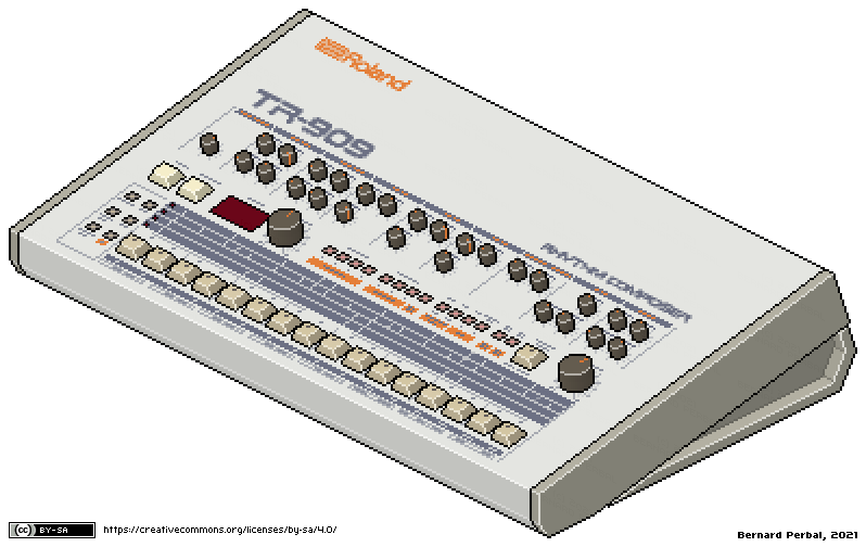
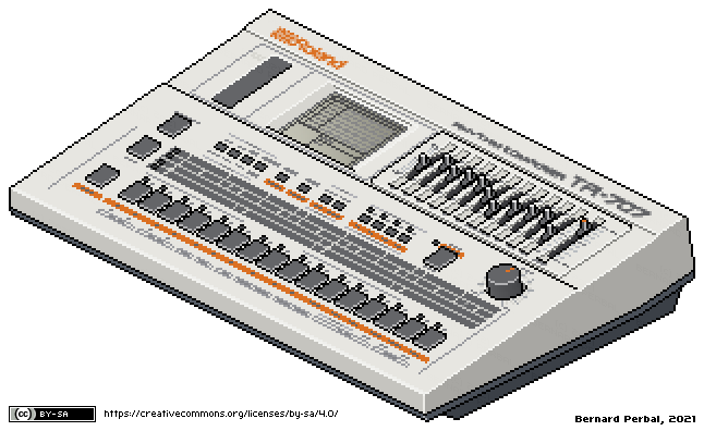
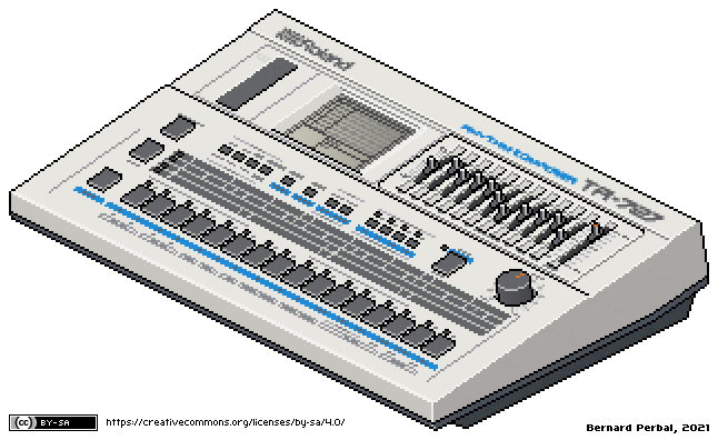
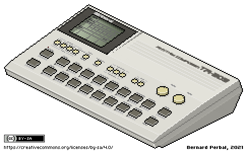
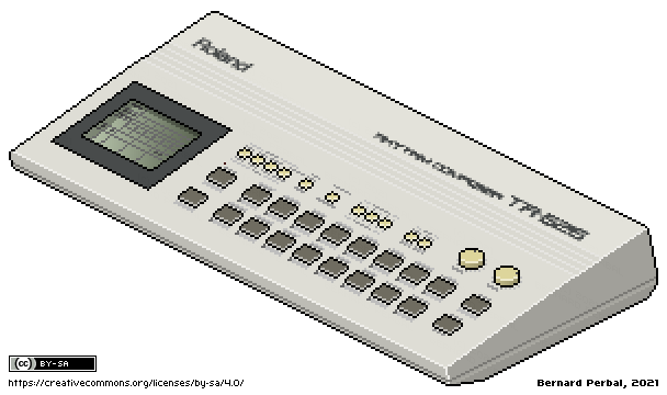
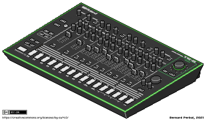
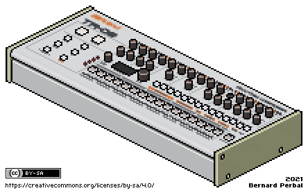
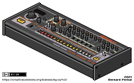
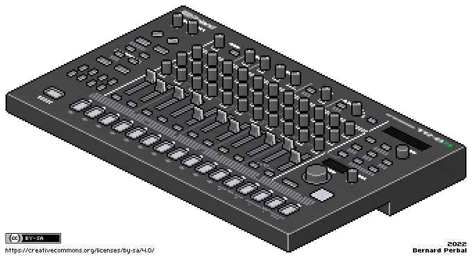
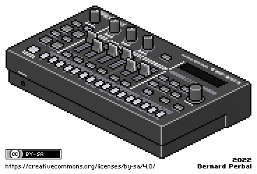
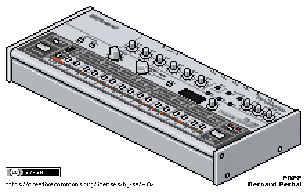
Quelques équipements de mon home studio réalisés en pixel art isométrique : Moog Mother-32 avec support 2 niveaux et 3 niveaux, Roland TB-303 and MXR Distortion+, Akai MPC60, Roland MKS-7, MacBeth Micromac-D, Teenage Engineering Pocket Operator TO-12 Rhythm, Roland TR-77, Roland TR-77V, Roland TR-33, Roland TR-55, Roland TR-330, Roland TR-700, Roland TR-66, Roland TR-808, Roland TR-606, Roland TR-909, Roland TR-707, Roland TR-727, Roland TR-505, Roland TR-626, Roland TR-8, Roland TR-09, Roland TR-08, Roland TR-8S, Roland TR-6S, Roland TR-06.
Sequential Circuits Drumtraks - Correction of I/O Address Annotations in the Service Manual
posted on 04 June 2026, updated on 09 June 2026
Summary
During reverse-engineering and hardware verification of a Sequential Circuits Drumtraks, I found that the I/O address annotations printed on the commonly circulated schematic appear to be incorrect.
The actual hardware decoding performed by U214 (74LS138) does not match the annotated addresses shown on the schematic.
This conclusion is based on:
Hardware Verification
U214 Address Decoder
U214 is a HD74LS138P (standard 74LS138).
Continuity measurements performed directly on the motherboard confirm:
| U214 Pin | Function | Connected To |
|---|---|---|
| 1 | A | Z80 A2 (pin 32) |
| 2 | B | Z80 A3 (pin 33) |
| 3 | C | Z80 A4 (pin 34) |
| 6 | G1 | Z80 A7 (pin 37) |
| 5 | /G2B | Z80 /M1 through LS04 inverter |
The /M1 path was verified:
Z80 pin 27 (/M1)
→
74LS04 pin 5
74LS04 pin 6
→
U214 pin 5 (/G2B)
Therefore the LS138 is enabled only during I/O cycles and not during instruction fetches.
LS138 Output Verification
Continuity measurements confirm:
| LS138 Output | Pin | Signal |
|---|---|---|
| Y0 | 15 | /OLEDS |
| Y1 | 14 | /OSINK |
| Y2 | 13 | /ODAC |
| Y3 | 12 | /OTRIGB |
| Y4 | 11 | /OTRIGA |
| Y5 | 10 | /OMISC |
| Y6 | 9 | /OSHMUX |
| Y7 | 7 | /OCNTR |
All outputs were verified on the physical motherboard.
LS138 Truth Table
Because:
| A | = | Z80 A2 |
| B | = | Z80 A3 |
| C | = | Z80 A4 |
and because the 74LS138 selects outputs according to:
| C | B | A | Output |
|---|---|---|---|
| 0 | 0 | 0 | Y0 |
| 0 | 0 | 1 | Y1 |
| 0 | 1 | 0 | Y2 |
| 0 | 1 | 1 | Y3 |
| 1 | 0 | 0 | Y4 |
| 1 | 0 | 1 | Y5 |
| 1 | 1 | 0 | Y6 |
| 1 | 1 | 1 | Y7 |
the actual decoded ports are:
| Address | Function |
|---|---|
| E0 | /OLEDS |
| E4 | /OSINK |
| E8 | /ODAC |
| EC | /OTRIGB |
| F0 | /OTRIGA |
| F4 | /OMISC |
| F8 | /OSHMUX |
| FC | /OCNTR |
Note that A6, A5, A1 and A0 are not decoded.
Therefore each function responds to multiple port addresses.
The addresses shown above are simply the canonical addresses used by the firmware.
Comparison with Published Schematic Annotations
Many copies of the Drumtraks schematic contain annotations similar to:
/OSHMUX @ E4H /OMISC @ E8H /OTRIGA @ ECH /OTRIGB @ F0H /OSINK @ F8H /OLEDS @ FCH
These annotations are inconsistent with the verified hardware decoding.
The corrected table is:
| Signal | Annotated Address | Verified Address |
|---|---|---|
| /OLEDS | FCH | E0H |
| /OSINK | F8H | E4H |
| /ODAC | F4H | E8H |
| /OTRIGB | F0H | ECH |
| /OTRIGA | ECH | F0H |
| /OMISC | E8H | F4H |
| /OSHMUX | E4H | F8H |
| /OCNTR | E0H | FCH |
Probable Cause of the Error
The annotated addresses appear to have been calculated assuming:
LS138 A <- A4 LS138 B <- A3 LS138 C <- A2
while the actual motherboard wiring is:
LS138 A <- A2 LS138 B <- A3 LS138 C <- A4
This produces exactly the observed reversal.
ROM Analysis (OS v0.5)
The ROM starts with:
0000: 3E 0F LD A,0FH 0002: D3 E4 OUT (E4H),A 0004: ED 56 IM 1
Initially this seemed to suggest that E4H must correspond to /OSHMUX.
However hardware verification proves that:
E4H → /OSINK
The first firmware output therefore targets the keyboard/LED scan circuitry.
Understanding the First OUT (E4H)
/OSINK drives the W/D (Write/Disable) inputs of two addressable latches:
U105 = 4099 U107 = 4099
The byte written to E4H is decoded as:
0FH = 00001111
For U107:
Address = 111 Data = 1
Therefore:
Q7 <- 1
A particularly interesting detail is that:
Q7(U107)
→
RES(U105)
RES(U107)
Thus the first firmware output immediately establishes a known reset state for the scan latches.
This makes far more sense than the previous assumption that E4H controlled the sample-and-hold multiplexer.
Conclusion
The physical motherboard, continuity measurements, LS138 truth table, and firmware analysis all support the following I/O map:
| Port | Function | Hardware Controlled |
|---|---|---|
| E0H | OLEDS | Two 4042 latch circuits (U102 and U103) driving the LED matrix |
| E4H | OSINK | Two 4099 addressable latches controlling the LED matrix (U105) and switch matrix (U107) |
| E8H | ODAC | 7524 DAC digital-to-analog converter (U226) |
| ECH | OTRIGB | Hex D-type Flip-Flop 4174 - Trigger Latch B (U219) |
| F0H | OTRIGA | Hex D-type Flip-Flop 4174 - Trigger Latch A (U217) |
| F4H | OMISC | Hex D-type Flip-Flop 4174 - Misc Output Latch (U216) |
| F8H | OSHMUX | Hex D-type Flip-Flop 4174 - Sample & Hold Address / Strobe Latch (U218) |
| FCH‑FFH | OCNTR | Intel 8253 Programmable Interval Timer (U211) |
The commonly circulated schematic annotations appear to contain a systematic reversal of the LS138 address bit order.
Additional Note Regarding the 8253 Timer (U211)
Unlike the other decoded devices, the Intel 8253 Programmable Interval Timer occupies four consecutive I/O addresses:
| Address | Function |
|---|---|
| FCH | Counter 0 |
| FDH | Counter 1 |
| FEH | Counter 2 |
| FFH | Control Register |
This is possible because the LS138 output OCNTR only generates the chip-select signal for U211.
The lower address bits A0 and A1 are connected directly to the 8253 address inputs and are therefore used internally by the timer to select one of its four registers.
Consequently, all addresses from FCH through FFH activate the same device (U211), while the specific operation performed depends on the values present on address lines A0 and A1.
This behavior differs from the other Drumtraks I/O devices, which ignore address lines A0 and A1 and therefore respond identically to all four addresses within their decoded address range.
Observations Regarding U212 (74LS04)
During the verification process, an additional discrepancy was found between the published schematic annotations and the actual motherboard wiring around U212 (74LS04).
Continuity measurements confirmed:
Z80 pin 27 (/M1)
→
U212 pin 5
U212 pin 6
→
U214 pin 5 (/G2B)
and:
U216 pin 12
→
U212 pin 13
U212 pin 12
→
CC OUT (via R222)
The available schematic annotations appear to interchange these two inverter sections.
While this discrepancy does not affect circuit operation, it demonstrates that some annotations in the available documentation should be independently verified against the physical hardware.
Exemple de schéma équivalent Thévenin dans le livre The Art Of Electronics de Horowitz and Hill
posté le 30.05.26
L'ouvrage The Art of Electronics de Paul Horowitz et Winfield Hill est largement considéré comme une référence incontournable en électronique pratique. Son premier chapitre présente les notions fondamentales relatives aux résistances et aux sources de tension.
La sous-section 1.2.5 est consacrée au théorème de Thévenin, selon lequel tout réseau linéaire composé de résistances et de sources de tension peut être remplacé par un circuit équivalent constitué d'une unique source de tension VTh en série avec une unique résistance RTh.
Le théorème s'applique aux réseaux linéaires. Les circuits comportant des composants non linéaires (diodes, transistors en régime non linéaire, etc.) nécessitent des précautions supplémentaires.
RTh représente la résistance interne vue depuis les bornes de sortie du réseau. Elle traduit la capacité du circuit à fournir du courant sans que sa tension ne s'effondre.
Ce principe est illustré par le schéma ci-après, lequel ne correspond pas à un montage réel ayant une utilité pratique particulière.
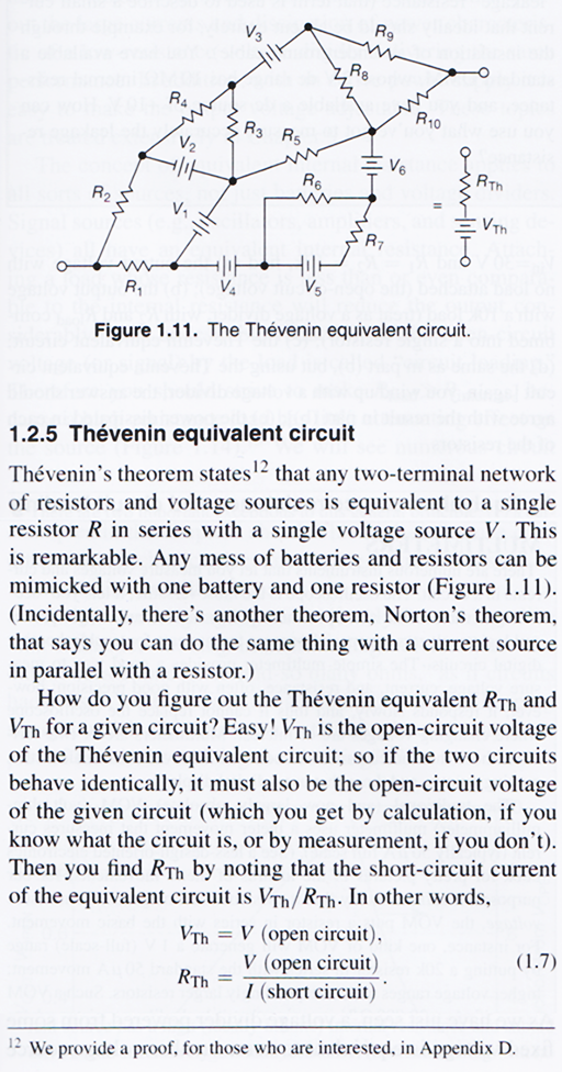
Il m'a semblé intéressant, à titre d'exercice, de déterminer l'équivalent de Thévenin (VTh et RTh) de ce réseau en attribuant arbitrairement des valeurs à chacun de ses composants.
A cette fin, les résistances R1 à R10 seront définies avec des valeurs comprises entre 100 Ω et 1000 Ω. De même, les tensions des sources V1 à V6 seront comprises entre 1 V et 6 V, en respectant les polarités indiquées sur le schéma.
L'équivalent de Thévenin sera calculé entre les points A et B. Pour faciliter les calculs, le potentiel de référence (0 V) sera arbitrairement placé au point E.
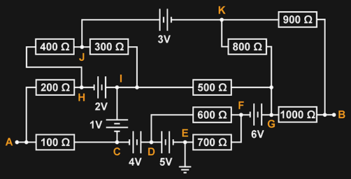
Première étape : calcul de la résistance équivalente RTh. Pour cela, il suffit de remplacer toutes les sources de tension par des conducteurs parfaits (résistance nulle), puis de remplacer les associations de résistances en série ou en parallèle par leurs résistances équivalentes.
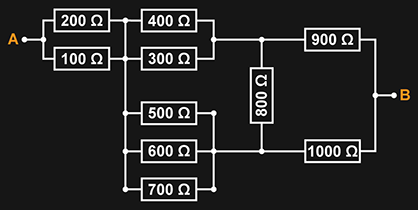
En réduisant les groupes de résistances en parallèle à leur résistance équivalente, nous obtenons :
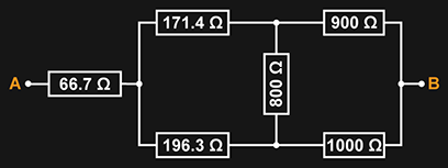
Ensuite, nous allons transformer les trois résistances de droite, disposées en triangle (800 Ω, 900 Ω et 1000 Ω), en leur équivalent en étoile. Nous obtenons alors :
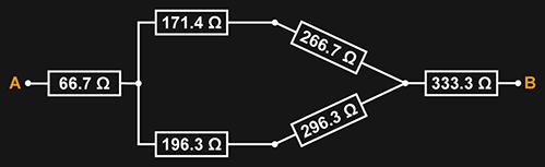
Ce qui donne :

En additionnant les valeurs de toutes ces résistances, nous obtenons la valeur de la résistance équivalente de Thévenin :
RTh = 631,9 Ω
Pour le calcul de la source de tension équivalente de Thévenin, nous allons conserver la transformation des trois résistances de 800 Ω, 900 Ω et 1000 Ω en leur équivalent en étoile. Le nouveau circuit est le suivant :
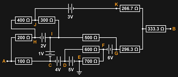
Notons que la tension au point situé entre les deux résistances de 266,7 Ω et 296,3 Ω est égale à la tension du point B, car ce point n'est relié à aucun élément du circuit. Aucun courant ne circule donc dans la résistance de 333,3 Ω.
Les tensions des points suivants sont facilement établies :
| VE = | 0.000 V | Réf |
| VD = | 5.000 V | |
| VC = | 1.000 V | VE - 4 V |
| VI = | 2.000 V | VC + 1 V |
| VH = | 0.000 V | VI - 2 V |
Au point A, nous avons :
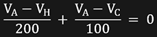
En remplaçant les valeurs connues de VH et VC, nous trouvons VA :
| VA = | 0.667 V |
Notons les points suivants :
| VG = | VF + 6 |
| VJ = | VK + 3 |
Au point K, nous avons :

Exprimons VK en fonction de VB :


Au point G, nous avons :

Exprimons VG en fonction de VB :


Au point B, nous avons :
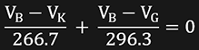
En remplaçant les valeurs de VK et VG, calculées ci-dessus, nous trouvons la valeur de VB : 1.872 V
La valeur de la tension équivalente de Thévenin est donnée par VTh = VA - VB.
L'équivalent de Thévenin de ce circuit est donné par les valeurs suivantes :
VTh = -1,206 V
RTh = 631,9 Ω
Statistiques Winamp
posté le 03.01.09
Statistiques des morceaux joués avec Winamp depuis le 26.12.08
Artiste : Ascendant
Cumul des Morceaux Joués : 148
Nombre De Morceaux : 57
Taux : 2.60
Morceaux Joués :
Ascendant - Voidstar joué 8 fois
Ascendant - Invoking The Vision joué 8 fois
Ascendant - Astral Nexus joué 7 fois
Ascendant - Astral Ascendant joué 7 fois
Ascendant - Astral Ascendancy joué 6 fois
Ascendant - Alignment joué 5 fois
Ascendant - Infinity Architect joué 5 fois
Ascendant - Origin Of Light joué 5 fois
Ascendant - Source Transmission joué 4 fois
Ascendant - Unveiled Sky joué 4 fois
Ascendant - Helios Drifts joué 4 fois
Ascendant - Adorations Of The Void joué 4 fois
Ascendant - Expansion joué 3 fois
Ascendant - Luminescence joué 3 fois
Ascendant - Unearth joué 3 fois
Ascendant - Solar Sea joué 3 fois
Ascendant - Solar Invocation joué 3 fois
Ascendant - Meridian joué 3 fois
Ascendant - Smoke Ring joué 3 fois
Ascendant - Liquid Memory joué 3 fois
Ascendant - Echoes Of The Source joué 2 fois
Ascendant - Vectors Of Return joué 2 fois
Ascendant - Coherence joué 2 fois
Ascendant - The Infinite Coil joué 2 fois
Ascendant - Scorpio joué 2 fois
Ascendant - Existence joué 2 fois
Ascendant - Remains joué 2 fois
Ascendant - Sub-Orbital Forest joué 2 fois
Ascendant - Radiance joué 2 fois
Ascendant - Elliptical Memory joué 2 fois
Ascendant - The Age Of Acceleration joué 2 fois
Ascendant - The Milky Seas joué 2 fois
Ascendant - Taking The Void joué 2 fois
Ascendant - Zero-Crossing joué 2 fois
Ascendant - Probability joué 2 fois
Ascendant - Twilight Gap joué 2 fois
Ascendant - Capacity joué 2 fois
Ascendant - Reactive Light joué 2 fois
Ascendant - Landfall joué 2 fois
Ascendant - Matter joué 2 fois
Ascendant - The Outer Dark joué 1 fois
Ascendant - Spiral Convergence joué 1 fois
Ascendant - Fragments Of The Code joué 1 fois
Ascendant - The Particle Horizon joué 1 fois
Ascendant - Gardens Of Light joué 1 fois
Ascendant - Edge Of The Infinite joué 1 fois
Ascendant - Gateway Aura joué 1 fois
Ascendant - The Age Of Earth And Stone joué 1 fois
Ascendant - Arcology joué 1 fois
Ascendant - Frozen Clouds joué 1 fois
Ascendant - Beams joué 1 fois
Ascendant - inStasis joué 1 fois
Ascendant - Electronic Mirror joué 1 fois
Ascendant - Ephemeris joué 1 fois
Ascendant - Fortran Drift joué 1 fois
Ascendant - Starfall joué 1 fois
Ascendant - Cosmic Forge joué 1 fois
© 2008-2026 perbal.net